CS4610: Lecture 9 - Arm Kinematics
Arm Coordinate Frames
- Recall from Lecture 3 that we defined a world coordinate frame (w in the figure below) that is fixed to the environment, with standard basis
 and origin
  . The
. The  axis of world frame points up from the ground, and we normally draw the
  axis pointing right and the
  axis pointing up.
 - We also defined a robot frame (r in the figure below) that moves with the robot. It has basis
 and origin
  at the point on the ground midway between the two wheel contact points. (The basis and origin vectors of robot frame are expressed in world frame coordinates.)
  (i.e. the axis of robot frame also points up from the ground),
  always points directly forward on the robot, and
  always points to the robot’s left.
  is the CCW positive angle from
  to (i.e. from the world frame axis direction to the robot frame axis direction).
 - We now define several coordinate frames on the arm (see figure below):
- Frame 0 is attached to link 0 on the arm, the initial link that is rotated by the arm shoulder joint. The axis of frame 0 points down link 0; the axis points to robot left, and the axis points “up” on link 0. The origin of frame 0 is the point where the arm shoulder rotation axis intersects the
 plane of robot frame, which is at the fixed location
  in robot frame.
 - Frame 1 is attached to link 1 on the arm, the second link that is rotated by the arm elbow joint. The axis of frame 1 points down link 1; the axis points to robot left, and the axis points “up” on link 1. The origin of frame 1 is the point where the arm elbow rotation axis intersects the plane of robot frame, which is at the fixed location
 in frame 0.
 - Frame 2 is attached to link 2 on the arm, the third link that is rotated by the arm wrist joint. This is also the link that carries the gripper. The axis of frame 2 points down link 2; the axis points to robot left, and the axis points “up” on link 2. The origin of frame 2 is the point where the arm wrist rotation axis intersects the plane of robot frame, which is at the fixed location
 in frame 1.
 - Frame g (gripper frame) is also attached to link 2; it models the point where an object could be gripped. It is co-oriented with frame 2, and its origin is the center of the circular notch between the gripper fingers, which is at the fixed location
 in frame 2.
- The arm joint angles are
 : the CCW positive angle from the direction of to
 : the CCW positive angle from the direction of to
 : the CCW positive angle from the direction of to
  .
. - Positive values of each rotate the arm down (i.e. these are right-hand-rule rotations about the corresponding axes).
- The ranges of motion are
 ,
, 
 ,
, 
 ,
,  .
. - The figure shows the arm in home pose which has
 ,
,  ,
,  , and the gripper closed.
 - We also define a calibration pose where the arm is pointing straight forward, i.e.
 and the gripper is closed.
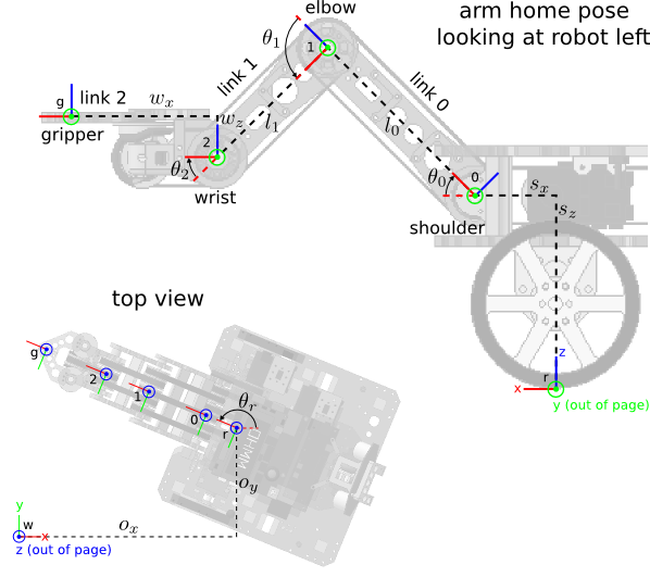
Forward Kinematics
- In Lecture 3 we also developed the forward position kinematics of the robot mobility, including a mathematical function with inputs
 (the robot pose) and output
  , a
, a  homogenous transformation matrix taking coordinates in robot frame to world frame.
 - We can restate this function using two components:
 is a pure translation transform
 is a pure rotation about the axis
- Then
 .
. - Remember, transforms compose from right to left. Given a 3D point
 in robot frame, transform it to world frame
  by appending an extra 1 and then left-multiply by :
- We now extend this function to include the arm; the inputs will be
 , and the output will be
  , a homogenous transformation matrix taking gripper frame to world frame.
 - Defining
 as a pure rotation about the axis, continue the composition to include transforms all the way from gripper frame to world frame:

- Using abbreviations
 and
and  , and observing that the product of a pure translation and a pure rotation (in that order) is given simply by copying the upper left
  submatrix of the rotation and the upper right
  submatrix of the translation,


 ,
, 
 ,
, 

- This shows that the transform taking gripper frame to robot frame is the product of a pure translation and a pure rotation:

- In other words,
- the orientation of the gripper in the robot frame
 plane is
  , i.e. the CCW positive angle from to
  is the sum of the joint angles
 - the gripper location in robot frame (the grip point) is

- in this case, both of these results could have been found directly using only basic trigonometry (in fact the derivation is very easy)
- but the transform composition formalism with homogenous transformation matrices works the same way for a very broad class of kinematic chains, not just this particular gripper, and it is efficient
Analytic Inverse Kinematics
- Just as inverse position kinematics was very useful for robot mobility, it will also be useful for the arm.
- Conceptually, we would like to literally invert the forward kinematic function.
- Recall that for robot mobility, this meant finding some drive trajectory that would bring the robot to a desired pose
 .
. - For the arm, we can define the inverse kinematic problem as finding a set of joint angles
 that put the gripper at a desired location
  and orientation
  in the robot frame plane.
 - Later, we’ll show a simple extension that also uses turn-in-place wheel motions to allow the arm to reach a 3D volume in world frame.
- We’ll make one simplification: we will only solve a version of the problem where
 . That is, we will solve a restricted version of the arm IK problem where the gripper is always held parallel to the ground. This simplifies the math somewhat while still demonstrating the essence of IK. Also, it’s not too much of a compromise in many practical grasping tasks.
 - Inverse kinematics is a well-studied area. There are a number of approaches; two common ones are analytic (or closed form) IK and numeric (or iterative optimization) IK. We’ll first demonstrate an analytic IK solution for our arm; later we’ll re-solve the problem using the numeric approach.
- The basic idea of analytic IK is to try to algebraically invert the forward kinematics equations. When this is possible (and it is not always possible), the approach has several key properites:
- Once the IK equations are found (on paper), they can be coded up, and at runtime their solution(s) can be found (by definition) in constant time. So analytic IK is usually fast.
- Note carefully: there can be more than one solution. For example, in our version of the problem, the elbow could “kink” up or down.
- Unreachable targets are also identified in constant time.
- Here’s one way to solve our version of the IK problem with an analytic approach:
- First, since
 , we can immediately derive
 (1)
(1)
- The same fact implies
 and
and  , which lets us simplify


to


- Now expand the trig identities for angle sums
 (2)
(2)
 (3)
(3)
- and add the two identities
 (4)
(4)
 (5)
(5)
- Tecnically (2–5) are a system of 4 equations in 4 unknowns (
 ), so we should be able to solve for all unknowns.
 - This is a little tricky unless we apply some geometric insight. Define the reach triangle with vertices given by the origins of frames 0, 1, and 2 (i.e. the intersections of the shoulder, elbow, and wrist rotation axes with the vertical plane in robot frame). Two of the triangle side lengths are
 and
and  ; the angle between those two sides is
  . Defining the reach vector as
 , the third triangle side has length
 (6)
(6)
- Apply the cosine angle difference identity and the law of cosines to solve for
 :
:
 (7)
(7)
 (8)
(8)
- If
 then (8) implies
  , but otherwise the given target is unreachable.
 - Assuming the target is reachable, use (5) to find
 , taking the positive branch of the square root to make the arm “kink up”, i.e. to find a solution with
  :
:
 (9)
(9)
- Together, (8–9) determine
 . (10)
- The target is unreachable if
 , otherwise continue.
 - The final job is to calculate
 . It will be the difference of the orientation
 (11)
(11)
of the reach vector and the angle  in the reach triangle between the sides with lengths and
  :
:
 (12)
(12)
- can be found by another application of the law of cosines:
 . (13)
- The target is reachable if .
- Finally, calculate
 by (1); the target is reachable iff .
 - Summing up:
 is calculated by (10), which depends on (6,8,9); then is calculated by (12) which depends on (6,11,13); and finally is given by (1).
- This approach can be extended to include a “yaw” rotation by using the wheels to turn in place, which allows the arm to reach a 3D volume in world frame.
- Let the 3D target location for the gripper be
 in world frame, and assume that the robot reference point is at the world frame origin.
 - Calculate the yaw angle
 .
. - Transform
 to
to  with the robot at orientation :

- This boils down to


where  is the distance from robot frame origin to the projection of the grip point on the ground plane, and
  are the coordinates of the grip point in robot frame.
 - Continue as above with the target in the robot frame plane.
Numeric Inverse Kinematics
TBD
